ACU-Controller
Control
Software for the
ACU-1000 and
the ACU-T
Software
Installation and Operation Manual
Designed and Manufactured by:
JPS Communications,
Inc.
5800 Departure Drive
Raleigh, NC 27616
Email: [email protected]
JPS P/N 5961-298200
Revision 4.01
April 2004
Warranty
JPS Communications, Inc. warrants
its manufactured equipment to be free from defects in materials and
workmanship, and to conform to published specifications for a period of 18 months
from the date of shipment from the factory or 12 months from installation,
whichever occurs first.
JPS warrants its service work performed in connection
with this warranty to be free from defects in materials and workmanship for a
period of 90 days from the date the work is performed.
If a defect occurs within the warranty period, the buyer
shall notify JPS immediately. JPS will repair or replace the equipment at its
option, upon return of the equipment; shipping prepaid, to the JPS facility in
Raleigh, North Carolina, USA.
This warranty does not apply to damage caused by
accidents, abuse or improper installation.
NO OTHER
WARRANTY, EXPRESSED OR IMPLIED, INCLUDING BUT NOT LIMITED TO THE IMPLIED
WARRANTIES OF MERCHANTABILITY AND FITNESS FOR A PARTICULAR PURPOSE, SHALL
APPLY.
NOTICE
JPS Communications, Inc. reserves
the right to make changes to the equipment and specifications without prior
notice.
PROPRIETARY STATEMENT
The information contained in this manual is the property of
JPS Communications, Inc. and is intended for the purchaser’s use only. It may
not be reproduced without the express written consent of JPS Communications.
Table of
Contents
1 Introduction & Installation. 1-1
1.1 Introduction. 1-1
1.2 Computer
System Requirements. 1-2
1.3 Installation. 1-2
1.4 Getting
Started. 1-2
1.4.1 Serial Remote Control 1-2
1.4.2 Ethernet Control 1-2
1.4.3 First Steps at Initial Start-Up. 1-2
1.5 Pull
Down Menus. 1-2
1.6 File
Menu. 1-2
1.6.1 Save Configuration. 1-3
1.6.2 Load Configuration. 1-3
1.6.3 Retrieve Current Configuration. 1-4
1.6.4 Restore Last Configuration. 1-5
1.6.5 Exit 1-5
1.7 Connect
Menu. 1-6
1.7.1 Select Network Site. 1-6
1.7.2 Select Serial Port 1-7
1.8 Options
Menu. 1-8
1.8.1 Pin Settings. 1-8
1.8.2 Password Protection. 1-9
1.8.3 View Recent Log. 1-9
1.8.4 View Entire Log. 1-9
1.8.5 New Log. 1-9
1.8.6 Connect All/Revert 1-9
1.8.7 Disconnect All/Revert 1-9
1.8.8 Voice Prompts On/Off 1-10
1.8.9 Right Mouse Button. 1-10
1.8.10 Connection
Indicator 1-10
1.8.11 Auto
Connect On Startup. 1-10
1.9 Permanent
Connections (PermConn) Menu. 1-10
1.10 Display
Menu. 1-11
1.10.1 COR/PTT
Reporting On/Off 1-12
1.10.2 Sound
On/Off 1-12
1.10.3 Hover
Icon Description. 1-12
1.10.4 Animations. 1-12
1.10.5 Screen
Size. 1-13
1.10.6 Change
Colors. 1-13
1.10.7 Set
Window Title. 1-13
1.11 Help
Menu. 1-13
2 Basic Operation. 2-1
2.1 Understanding
the Main Screen. 2-1
2.1.1 Module Grid. 2-1
2.1.2 Column Heading Area. 2-1
2.1.3 Net Area. 2-1
2.1.4 Connection Indicator 2-2
2.1.5 Message Areas. 2-3
2.2 Making
and Breaking Connections. 2-4
2.2.1 Normal Connections (Nets) 2-6
2.2.2 Vertical Connections. 2-7
2.2.3 Priority Connection. 2-9
2.2.4 Monitor Connections. 2-12
2.2.5 Permanent Connections. 2-15
2.2.6 Ethernet Connections via the NXU-2. 2-15
2.3 PSTN-1
Operation. 2-16
2.3.1 Placing a Telephone Call Using the PSTN. 2-16
2.3.2 Storing Phone Numbers. 2-17
2.3.3 PSTN-1 Operation with Four-Wire Circuits. 2-17
2.3.4 PSTN-1 Operation with Two-Wire Leased Lines. 2-18
2.4 System
Operation at Power-Up. 2-18
2.4.1 System Operation when ACU Power Is Cycled. 2-18
2.4.2 System Operation when ACU Controller Is Cycled. 2-19
2.5 Sample
Log File. 2-20
2.6 Multiple
ACU Controller Operation. 2-21
2.6.1 Simultaneous Commands. 2-21
2.6.2 Special Considerations - Multiple ACU Controllers. 2-21
3 Module Settings. 3-1
3.1 General. 3-1
3.2 Entering
the Module Settings Screen. 3-1
3.3 Changing
Module Settings. 3-1
3.3.1 Icon Color Choices. 3-2
3.3.2 Apply Text to Icons. 3-2
3.3.3 Installing Custom Icons. 3-2
3.3.4 Module Settings Storage. 3-2
3.4 Templates. 3-2
3.4.1 Templates Supplied by Raytheon JPS. 3-2
3.4.2 User-Created Templates. 3-2
3.4.3 Saving Templates. 3-3
3.4.4 Loading Templates. 3-3
3.4.5 DSP Help. 3-4
3.4.6 Browsing Application Notes. 3-4
3.5 Special
Provisions, PSTN-1 Settings Screen. 3-5
4 PIN SECURITY & PASSWORDS. 4-1
4.1 Pin
Security. 4-1
4.2 Passwords. 4-2
4.2.1 Lost or Forgotten Passwords. 4-3
5 Using the Keyboard. 5-1
5.1 General. 5-1
5.2 Simulating
Mouse Input. 5-1
5.3 Menu
Commands. 5-2
5.4 Other
Commands. 5-4
6 Advanced Topics. 6-1
6.1 General. 6-1
6.2 Understanding
Serial Communication with the ACU. 6-1
6.3 Customizing
Sounds. 6-2
6.4 Restoring
Default Preferences. 6-2
6.4.1 Factory Default Settings. 6-2
6.5 Pop-Up
Messages. 6-1
6.5.1 Can't Make Connection: Conferencing Not Enabled. 6-1
6.5.2 Confirmation Doesn't Match
Password Entry. 6-1
6.5.3 Create Window Error 6-1
6.5.4 Connect All: Are You Sure?. 6-1
6.5.5 Disconnect All: Are You Sure?. 6-1
6.5.6 Error Opening New COM Port 6-1
6.5.7 Failed to Register Window Class. 6-1
6.5.8 Retrieve Current Configuration from
ACU First 6-1
6.5.9 Incorrect Password. 6-1
6.5.10 Load
Failed! Saved Configuration not Compatible with Current Configuration 6-1
6.5.11 Load
Failed! Wrong File Version. 6-1
6.5.12 Load
File Could Not Be Opened. 6-1
6.5.13 No
COM Port is Currently Open. 6-1
6.5.14 New
COM Port Selected. 6-1
6.5.15 New
Preferences File Created. 6-1
6.5.16 No
Data to Save. 6-2
6.5.17 No
Default Text Viewer in Registry. You
Will Have to Open the File Manually 6-2
6.5.18 No
More Audio Busses Available. 6-2
6.5.19 No
New Log File Selected. 6-2
6.5.20 Password
Changed. 6-2
6.5.21 Password
Cleared. 6-2
6.5.22 Reset
Configuration: Are You Sure?. 6-2
6.5.23 Save
File Could Not be Opened. 6-2
6.5.24 Template
File Could Not Be Opened. 6-2
6.5.25 Template
File is the Wrong Type. 6-2
6.5.26 The
ACU 1000 Software Is Not Compatible With This Version of the ACU Controller 6-2
6.5.27 The
Password Must Be At Least 4 Characters. 6-2
6.5.28 The
Phone Book Is Full 6-2
6.5.29 View
Log Failed. 6-2
7 APPENDIX. 7-1
7.1 Revision
History. 7-1
7.1.1 Revision 4.0. 7-1
7.1.2 Revision 3.12. 7-1
7.1.3 Revision 3.11. 7-2
7.1.4 Revision 2.00. 7-2
8 Index. 8-3
|
Glossary
|
|
AP-1
|
Audio Processor Module, applies a variety of functions to
other ACU-1000 or ACU-T module inputs or outputs, mainly used for additional digital
delay.
|
|
COR
|
Carrier Operated Relay - A receiver signal that indicates that a carrier or signal is
being received and the receiver is unsquelched. Same as COS.
|
|
COS
|
Carrier Operated Squelch - See COR.
|
|
CPM-2
|
Control Processor Module - This ACU module controls all
aspects of system operation.
|
|
DTMF
|
Dual Tone Multi Frequency - The standard touch-tone
telephone dialing method sends DTMF characters over the PSTN line.
|
|
DSP
|
Digital Signal Processing (or Processor).
|
|
DSP-1
|
The Digital Signal Processor Module, the main radio
interface of the ACU system. DSP algorithms
provide VOX, VMR, Audio Delay, Noise Reduction, and Tone Keying functions.
|
|
EIA
|
Electronic Industries Association.
|
|
Extension
|
Each interface module in the ACU system is given an
extension number. A user enters this
extension number to make a communications link through the selected module.
|
|
Hang Time
|
A system with hang time will remain in the transmit mode for
the duration of the set hang time beyond the time indicated by any keying
inputs. The hang time prevents
transmitter unkey during brief pauses in the transmission.
|
|
HSP-2
or
HSP-4
|
The ACU Handset/Speaker/Prompt Module. It provides a local operator
interface. System voice prompt
creation circuitry also resides on this module.
|
|
Key
|
To key a transmitter means to cause it to transmit.
|
|
LED
|
Light Emitting Diode.
|
|
LMR
|
Land Mobile Radio.
|
|
LP-1
|
The Local Phone Module in the ACU system.
|
|
Mute
|
To quiet or inhibit audio.
|
|
NXU
|
Network Extension Unit.
JPS device for interconnectivity with Ethernet.
|
|
PCB
|
Printed Circuit Board.
|
|
PIN Number
|
Personal Identification Number. When PIN Security is enabled, only users who enter a valid PIN
are allowed to access the ACU system.
|
|
Port
|
The rear panel connectors P1 through P12 (ACU-1000) or side
panel P0 through P5 (ACU-T) provide Communications
Ports to interface with other communications equipment (such as radios).
|
|
PSTN-1
|
The ACU module to interface to the Public Service Telephone
Network
|
|
PTT
|
Push-to-Talk. An
active PTT signal causes a transmitter to key.
|
|
RDI-1
|
The ACU module to interface with radios and other 4-wire
devices; includes an RS-232 port but no DSP features.
|
|
RX
|
Receiver or Receiving.
|
|
Slot
|
A physical location in the ACU chassis where a module can
be inserted.
|
|
Squelch
|
A means of detecting audio and causing some action when it
is present, such as keying a transmitter or unmuting an audio path.
|
|
Template
|
A template file contains all of the settings for an ACU-T
or ACU-1000 Interface module. It may
be called up to quickly apply the same settings to another module that is
being configured. Used mainly with
the DSP module for radio interfacing.
|
|
TX
|
Transmit or Transmitter.
|
|
VMR
|
Voice Modulation Recognition. A type of squelch, which is activated only by spoken words and
not by tones, noise, or other audio information.
|
|
VOX
|
Voice Operated Xmit (Transmit). A circuit or algorithm, which causes a transmitter to key or
some other action when voice is present.
This squelch type is activated by any audio signal, and is not
restricted to voice only.
|
.
The ACU Controller is a graphical control interface for the
ACU-1000 and the ACU-T (they will be given the common name “ACU” in this manual
for simplicity). It allows its operator
to quickly make and break several types of module-to-module interconnections,
modify module setups, save and load various configurations of the ACU system,
and take advantage of many other features designed to improve the functionality
of your ACU system. It’s possible to
simultaneously run several instances of the ACU Controller, with each instance
providing control of a different ACU.
The ACU Controller can control an ACU either via serial RS-232; or via
Ethernet, for any ACU that is connected to the network with an ETS-1 Ethernet
To Serial converter located at the ACU.
Note: This manual is
intended as a companion to the ACU-1000 or ACU-T manual, not as a
replacement. Proper setup of the system
will require a thorough understanding of the ACU and the ACU manual. Once the ACU system is setup, this manual is
all that is required to fully understand its operation via the ACU Controller
program. Ethernet control of an ACU may
also require thorough understanding of the ETS-1 manual.
In order for the ACU Controller to run on your computer,
these requirements must be met:
§
The operating system is Windows 95, Windows 98, Windows
Me, Windows NT, Windows 2000, or Windows XP
§
The video card and display support at least one of
these resolutions: 800x600, 1024x768, or 1280x1024
§
At least 64MB of RAM
§
50MB of free hard drive space
§
A serial port dedicated to the ACU for RS-232
communication
§
For Ethernet control of an ACU (or group of ACUs), the computer
must have an Ethernet card or other means to access the same network that the
ACU units are connected to. The
computer must have TCP/IP network protocol capability.
The use of a mouse is recommended, but not required
(operation is also possible via keyboard or touch screen.)
Note: Proper operation
of the ACU Controller requires that the CPM-2 module of the associated ACU
contains firmware revision 1.16 or higher.
To install the ACU Controller, insert the ACU Controller CD
in your CD-ROM drive. The installation
program should start automatically and guide you through the installation
process. You can also run the
installation program manually. It is
called “Setup.exe” and is located in the root directory of the ACU Controller
CD-ROM.
The Part Number for the ACU Controller Option, which consists
of the ACU Controller CD-ROM and a copy of this manual, is 5961-298100.
Before running the ACU Controller, make sure the serial cable
is plugged into both the computer and the ACU.
The serial cable must remain connected at all times during operation.
You can launch the ACU Controller either before or after the
ACU has been turned on.
If the ACU to be controlled will be connected to the computer
by an RS-232 serial connection rather than by Ethernet, the first time you run
the ACU Controller, you will need to select a new serial port if the default,
COM1, is not the correct port. The ACU
Controller will notify you whenever it cannot communicate via the selected
serial port. In addition, if everything
seems to be correctly set, but no module icons appear in the grid, the COM
setting may be wrong. COM1 is usually
the correct port.
To control an ACU via Ethernet, it will be necessary to enter
the IP address and port associated with the ACU that is to be controlled. The ACU must be connected to the same
network as the computer running the ACU Controller. The ACU network connection is made by the JPS ETS-1 (Ethernet
To Serial Converter). The
IP address and associated port number are configured in the ETS-1. The default port number for the ACU
Controller (23) is also the default port number configured in each ETS-1, so a
change is not required at the ACU Controller unless the ETS-1 default is
changed.
With the ACU Controller running, the first step is set the
proper screen size, then set the other preferences as necessary. Set any desired security (password
protection) provisions (see Section 4).
The following subsections give a basic understanding of each
of the pull-down menu options. In some
cases, it provides references to other sections explaining the features in
detail.
The File Menu has five options:
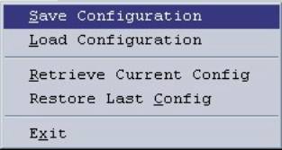
Figure 1‑1 File
Menu
This gives the user the option of storing the current
configuration in a file so it can be recalled later. The Configuration saved includes any nets (module-to-module
connections), the current settings of each module, PIN security and speed dial
databases, and any customization the user has made to the screen, including
icon colors, text added to icons, custom icons, etc. The user is prompted to save the current configuration via
standard Windows methods, making it easy to name and store the configuration in
the proper location. The correct
extension “.acu” is automatically appended.
By default, the configuration files are stored in the “Configurations”
directory, although another directory may be specified by the user. The current configuration is always
automatically saved when the program is exited (see 1.6.4).
This menu option is selected when the user wants to set the
ACU Controller to one of the configurations that has been saved via the “Save
Configuration” command.
Note: The
configuration selected by the Load Configuration command must be made up of a
similar complement of ACU modules, in the identical locations, as are installed
in the actual ACU.
The program will attempt to load configurations for setups,
which are similar, but if the system is different from what the configuration
was when saved, an error message will be displayed. For example, if additional modules have been added to the ACU chassis
since the configuration was stored the Load Configuration process will be
successful. This is because the
initially installed modules have not been moved or deleted, so the program can
run the Load Configuration feature with respect to these modules, ignoring the
new modules. If the locations of some
module types have changed (for example, if the locations of a DSP-1 module and
a PSTN-1 module are swapped), it will not be possible to load the
configuration.
This option commands the program to interrogate the ACU
regarding its current configuration and set the ACU Controller to match. This option should be rarely if ever
needed. It may be used, for example, if
the serial remote control cable is temporarily lost and the program becomes out
of sync with the ACU (because changes have been made in the interim at the
ACU), or if the ACU Controller shows no module icons despite a proper serial
connection.
Use this option to revert to the configuration the ACU
Controller was in when it was last powered down. Whenever the ACU Controller is shut off, it stores its current
configuration. When turned back on (if
no other configuration is installed via the Load Configuration command) it
reverts to the last stored setup parameters that relate to how the computer
screen looks (icons, background color, screen size, animation speed, etc.). However, the program does not return to
either the module-to-module interconnect scheme or the internal module settings
that existed when it was turned off.
Instead, it adopts the current conditions of the ACU that it is
controlling.
After the ACU Controller was powered down, it is possible
that the ACU internal settings were changed via the HSP-2 or that
module-to-module interconnections may have been created by the HSP-2 or via
DTMF from outside users. In addition,
the entire communications scenario may have been changed since the ACU
Controller was powered down, with the whole system moved to a new
location. Therefore, previous
interconnections and settings are not restored without an explicit Restore Last
Configuration command from the operator.
When selected, this command returns the ACU fully to the state it was in
when the ACU Controller was last shut down.
The only exceptions are the dynamic PSTN-1 connections, as they rely on
a system user taking a handset off-hook, or may have been initiated by an
unidentifiable outside user. For
instance, if someone calls into the ACU via a telephone, the ACU Controller
does not know the telephone number and cannot re-establish the connection.
Note: Before the ACU Controller can Load or Save
any configurations, serial communications must be established with the ACU.
This selection (or the “X” box in the window’s upper right
corner) may be used to shut down the ACU Controller program.
This pull-down menu provides options for connecting the ACU
Controller to an ACU-1000.
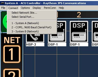
Figure 1‑2 Connect Menu
Note that at the top of the ACU Controller Main Screen, the
name of the currently connected site is displayed. A recently connected site list (up to 10 different sites) also
appears to allow quick connections to these sites. For connections to new sites, the “Select Network Site” and
“Select Serial Port” options are provided.
If the ACU Controller will be controlling an ACU-1000 via
Ethernet, chose the Select Network Site option to bring up a dialog box to
configure the connection. The top
portion of the Select Network Site dialog box has blanks for entering a new IP
address and port. (See also 1.7.1.1).
Entering a description is optional but recommended, as the description will be
displayed at the top of the screen, allowing the user to quickly see which
ACU-1000 is being controlled in a multi-ACU-1000 system. Once these items are typed in, click the Add button to add the new site to the
list that the ACU Controller will store in the preferences file (also shown in
the dialog box under “Stored Network Sites”).
Clicking the Add and Connect
button will add the site to the list, then attempt to connect to that new site
immediately and close the dialog box.
Sites entered by the user are displayed in the lower portion
of the dialog box; up to 500 sites can be stored. To connect to a site in the list, click on a site in the list,
and then click the Connect
button. The dialog box will close
immediately. While the Controller is
attempting to connect to a site, its window title will change to “Connecting….”
Once the connection is made, the window title at the top left of the screen
will change to the site’s stored description.
If no description was entered, the IP address will be displayed instead.
A site can be removed from the stored list by first clicking
on it in the list to select, then clicking the Remove button. Note that if
the Controller is currently connected to a network site, that site cannot be
removed from the list until the network connection is changed.
At start-up, the ACU-1000 can be set to either:
·
Automatically attempt to reconnect to the site it was
last connected to.
·
Require the operator to establish any Ethernet
connections
See Sec 1.8.11 for information regarding automatic connection
options.
Note: Once connected
to a network site, any icon colors, custom icons, or module names specified by
the user will be automatically associated with that site and will be loaded
whenever the ACU Controller reconnects to that site. This allows the user to switch between a multiple ACUs at
different network sites without having to save the current configuration before
switching, and then reload it when returning to that site.
This feature is available for Ethernet control only, not for RS-232 serial control.
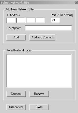
Figure 1‑3 Select Network Site Dialog Box
1.7.1.1
Port Selection for IP Address
As can be seen in Figure 1.3, the default port selection
associated with each IP address is 23.
Each ACU-1000 that can be controlled by the ACU Controller via Ethernet
is itself connected to the Ethernet network via a JPS Communications ETS-1
unit. The ETS-1 is an Ethernet To
Serial converter that connects the ACU-1000’s serial port to the network
(LAN, WAN, Wireless LAN, Internet, etc.).
The default port selection for each ETS-1 is also 23. To connect to and control an ACU-1000, the
ACU Controller needs both the IP address and port number of the ETS-1
associated with that ACU-1000. The
ETS-1 port selection may need to be changed, for example, if there are a number
of ETS-1/ACU-1000 systems that share the same IP address. See the ETS-1 manual for full details.
Note that the ACU Controller stores Network Site Addresses
and names whenever a new connection is made.
To connect to any of these stored sites, highlight and click the
“Connect” button.
For a serially-controlled system, this option allows the user
to set which of the host computer’s serial ports will be used to communicate
with the ACU-1000 for this version of the program. Users wishing to control multiple ACU-1000s might have multiple
instances of the ACU Controller program running concurrently; each will need to
communicate via a different serial port.
The default is COM1. This
selection need be made only once, the first time the ACU Controller is run, unless
using a different serial port becomes necessary. The serial port selection will be saved in the preferences file.
The default Baud Rate for the CPM-2 is 9600 Baud, and this
setting should be used unless other instructions are given.
Figure 1‑4 Serial Port Selection Dialog Box
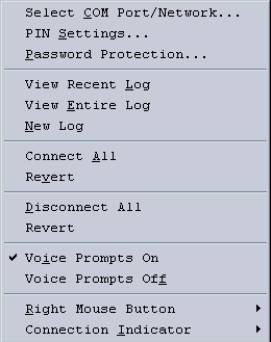
This pull-down menu gives the user the control of a wide
variety of system setup, control and monitoring options.
Figure 1‑5 Options
Menu
This menu option provides access to the database that sets
PIN numbers, User IDs, and Security Levels.
See section 4.
Access to this database may be Password Protected; see
Section 4.2 and Section 1.8.2.
This menu option opens the Password Dialog Box. This allows the user to set which (if any)
of the following require a password to modify:
§
ACU PIN Settings Database
§
Permanent Connections
§
Module Settings
See Section 4 for full information regarding PIN Settings and
Password Security. See Section 2.2.5
for an explanation of Permanent Connections.
Module Settings are covered in Section 3.
The Password Protection Feature allows the system to be set
up as desired and then turned over to an operator, with important aspects of
the feature placed outside of the operator’s control.
The ACU Controller maintains a log of all basic system
operations:
§
What connections are made
§
For PSTN connections, the phone number dialed and
whether the connection succeeded
§
The User ID if Password Security is in place
§
The time and date of each activity
This information is recorded in a Log File. The View Recent Log option brings up the
last 30 log entries in reverse chronological order (i.e., the most recent
activity at the top of the list).
The View Recent Log option may be selected over the View
Entire Log option if, for example, the ACU Controller operator is forced to
leave the computer for a while and, on his return, wishes to review the
activity that took place during their absence.
The ACU Controller will use the computer’s default text editor to
display the file. If for some reason,
no default text editor is specified, the log files can be opened manually. Look for the log files in the ACU Controller
installation directory. They all have
the “.log” extension. A sample log file is explained in Section 2.5.
This opens the log, which can be very lengthy if the New Log
option is seldom used. The full log is
displayed in chronological order, first activity at the top of the list. See the View Recent Log option above to see
only the most recent activity.
Select this to get the ACU Controller to start a New
Log. The user will be prompted to enter
a name for this new log file and from then on all activity will be stored in
this new file. The previous log file
remains stored, and can be manually accessed at any time.
When selected, Connect All causes all of the ACU modules to
be interconnected in a single net, except for any currently unconnected PSTN-1
modules. If any PSTN-1 modules are
currently connected in any net, they will remain connected. When Revert is selected, the single net is
dissolved, disconnecting all modules, and then all modules (except PSTN-1
modules) are returned to the nets they were in prior to the Connect All. The program is unable to reconnect the
dynamic PSTN-1 connections, since for example; the connection may have resulted
from an outside user calling into the system.
The ACU Controller has no record of the phone number of the caller and
hence cannot re-establish the connection.
When selected, Disconnect All dissolves all current
interconnections (nets). When Revert is
selected, all modules (other than PSTN-1 modules, see section 1.8.6) are returned to whatever nets they were in prior to
the Disconnect All.
This menu selection controls the ACU voice prompting. The default selection is On, with voice
prompts aiding system users to understand system status and changes. Please note that voice prompts are sent out
only in response to external users who attempt to gain access to the system via
DTMF, and not in response to activity commanded by the ACU Controller. Even
this voice prompting is sometimes not desired (for example, when system users
are involved in surveillance or public safety operations where silence is
required most of the time).
This menu selection allows the right mouse button to be
configured to either disconnect any module the cursor is right-clicked on, or
else to bring up the module’s settings screen.
§
If the right mouse button is set to disconnect nets,
the module settings screens can be viewed by double-clicking the appropriate
icon with the left mouse button. In
this mode, an operator can quickly connect and disconnect modules with a
minimal number of mouse clicks. Keep
the Connection Indicator set to “+” and use the left mouse button to connect
two modules by clicking on each in succession, then disconnect quickly with the
right mouse button.
§
If the right mouse button is configured to bring up the
module setting screens, a module can be quickly disconnected by left clicking
on its icon when the Connection Indicator is in the disconnect mode (see
section 1.8.10).
The connection indicator resides in
the upper left corner of the standard screen.
When it is a plus “+” sign,
left clicking on two modules in succession will create a net between those two
modules (See Section 2 for more complete details). When the Connection Indicator is a minus “-” sign, any module that is left clicked will be removed from its
existing net. There are two options for the way the connection indicator is
used:
§
Remain in its current “+” or “-” state until
it’s toggled (by a left click)
§
Return to “+”
after each time it’s used to disconnect a module
This option
determines what the ACU Controller does at program startup regarding connections. When set to “On”, the ACU Controller will
attempt to automatically restore its last successful connection (either Network
or Serial). If there was no existing network
or serial connection when the program was terminated or the computer power shut
down, the program will still attempt to restore its last successful
connection. Alternatively, the Auto
Connect at Startup feature can be set to “Off”, and no connection is made until
commanded by the ACU Controller operator.
This menu is used whenever a net is assigned “Permanent
Connection” status (see Section 2.2.5).
When any one of the Nets, 1 through 7 is selected via this pull-down
menu, the net becomes a Permanent Connection.
The Permanent Connection selection acts as a toggle. If the selected net does not currently have
Permanent Connection status, the selection will apply it. If the net already is set as a Permanent
Connection, the selection of this net via the PermConn menu will remove the
Permanent Connection status.
Figure 1‑6 Permanent
Connections Menu
This pull-down menu allows the look and sound of the ACU
Controller to be customized.
Figure 1‑7 Display
Menu
This selection decides if the current COR or PTT status of
each module will be displayed on its icon by a small additional icon in the
upper right quadrant. (See Figure 1.5; it shows full duplex activity with both of these
icons simultaneously on; in most cases, only one will be seen at a time).

Figure 1‑8 COR
& PTT Icons
The sound effects accompanying most basic ACU controller
actions help provide a positive or negative indicator of current activity, and may
be turned off if desired. Custom sound
effects may be installed in place of the set provided. See section 6.3.
When this feature is selected and the cursor is placed over a
Module Icon, the full Icon Description will be displayed. If this feature is disabled, only the
initial characters of the description (those that fit under the icon) are
shown.
Use this menu selection to change the speed of the
animations, which accompany changes to the connections displayed on the main
screen. The animations are intended to
provide the operator with visual cues to screen changes. The best way to determine the optimum
animation speed is simply to experiment with the settings. The four choices are
Slow (700ms), Medium (500ms), Fast (300ms), and Off, which means “No
Animations”; the changes will be instantaneous.
Use this menu selection to appropriately size the ACU
Controller screen to the monitor being used.
This selection will probably not be required as the ACU Controller is
automatically configured to maximize.
This selection allows the operator to change the background
and grid colors of the main screen.
Several presets are provided, along with infinite variability. One of the grid selections is “Match
Background”; this allows the grid to be removed from sight completely for
operators who would rather not have a grid.
This selection allows the customization of the title at the
top of the ACU Controller Window (the same title is displayed on the Windows
task bar). This title is saved whenever
a configuration is stored. Different
Window Titles may be particularly useful if multiple instances of the ACU
Controller are simultaneously open, controlling several ACUs.
Use the Help pull-down menu to access an HTML version of this
manual. The computer must have a Web
Browser in order for this manual to be viewed.
To enhance system security, the HTML manual will not include the
instructions telling how to change the system password that are included in
this printed manual.

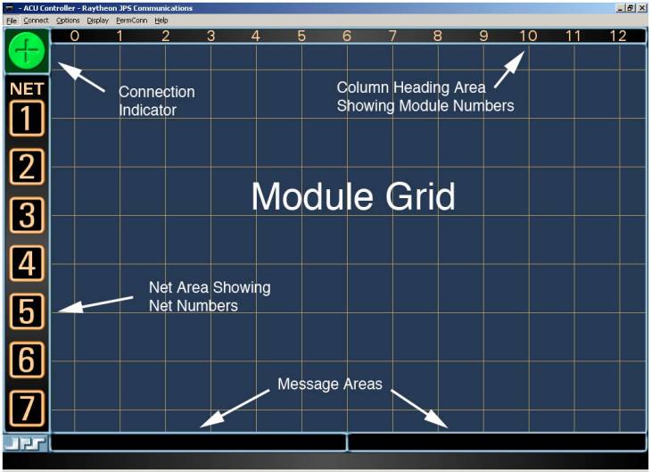
There are six parts to the main screen:
§
Module Grid
§
Column Heading Area
§
Net Area
§
Connection Indicator
§
Message Area 1
§
Message Area 2
These are described below and labeled in Figure 2‑2.
The module grid contains an icon representation of the HSP
module as well as each interface module in the ACU system. Five different module types are supported:
HSP-2 or HSP-4, DSP-1, RDI-1, PSTN-1, and LP-1. All modules of these types will appear as icons on the
screen. Other installed module types
will not show up. In particular, AP-1
modules have the ability to perform a number of DSP functions on their
throughput audio, but are not controlled by the CPM-2 module and cannot be used
to make connections. The AP-1 modules
are not recognized by the ACU or the ACU Controller and do not show up on the
module grid.
The horizontal position of each icon indicates the
corresponding module’s physical position in the ACU chassis (and its extension
number). See the next sub-section, The
Column Heading Area, for details.
The vertical position of each icon indicates the net in which this particular module
resides. A “net” is a group of two or
more modules interconnected (communicating with each other). Modules at the very top are not in a net (this
is called the “idle row” of
unconnected modules). Each net has an
associated net number (1 through 7),
listed along the far left in the net area.
The module grid is the main interface for making and breaking
connections if you are using a mouse or touch screen.
This area, which stretches across the top of the screen, has
a numerical heading for each column.
Each extension in the ACU is represented by a column on the screen. For example, an icon in column 5 in the grid
is associated with a module installed in extension 05 of the ACU. With a single ACU-1000, the columns will be
numbered 0 to 12, with the HSP associated with the “0” column at the far
left. (The extension number for the HSP
is “00” for local “Operator”) In
systems where two ACU-1000 chassis are connected together in the
master/expansion configuration, there are 26 columns. If an HSP is installed in the expansion chassis, it will be
represented by an icon in the column at the far right, at its extension number
25. Physical positions 1 through 12 in
the expansion chassis are represented by their extension numbers 13 through 24
in the column heading area.
For an ACU-T, along with the HSP module, there can be a
maximum of five interface modules installed; so the columns number simply 0
through 5.
The column heading area is also the interface for entering
the Monitor Mode. To do so, click on
the number of the Monitoring Module.
See Section 2.2.4.
This area consists of seven numbered net icons arranged
vertically down the left side of the screen.
When a net contains modules, a net
line will appear, stretching horizontally from the net number icon to the
right edge of the screen. Any module
icons positioned on the net line are members of that particular net. All modules that are members of a net are
interconnected (communicating with each other). A thin green net line indicates a normal connection between the
modules. Thicker blue, red, or yellow
net lines indicate Vertical Connections,
where different nets are connected with each other. Further explanation is provided in Section 2.2.2.
If you are using a mouse or touch screen, the net number
icons form the interface for simultaneously dealing with an entire net of modules.
The connection indicator is the square box in the upper left
corner of the screen. It indicates
whether the program is in the Connect
Mode or in the Disconnect Mode. A green circle around a plus sign is shown
for Connect Mode. Disconnect Mode is
indicated by a red circle around a minus sign.
The current mode setting determines how the program will respond to
clicks of the left mouse button (or clicks on the touch screen) on module icons
or net number icons. Generally, when
the program is in the Connect Mode, clicks on icons will result in the creation
of new connections. When in Disconnect
Mode, clicks on icons will break connections.
To toggle the current mode, click on the connection indicator.

Figure 2‑1 Connection
Indicator
Note: It is also possible to quickly make and
break connections with the mouse’s left and right buttons, skipping steps and
ignoring the Connection Indicator completely.
See 1.8.9 for details.
Note: An optional mode sets the Connection
Indicator so after a connection is broken when in the Disconnect Mode; the
indicator automatically reverts to the Connect Mode. See 1.8.10 for instructions.
The two message areas provide a variety of information to the
ACU Controller operator. Message area 1
is at the bottom of the screen on the left, message area 2 on the right. The first message area is mainly used to
display the full description of a module when it is selected or when the mouse
cursor passes over its icon. The second
displays various messages in response to certain commands from the program
operator or from the ACU.
These areas are the only parts of the screen that do not
respond to any type of operator input.
Figure
2‑2 Main Screen Areas
2.2
Making and Breaking Connections
There are five ways to connect ACU modules to each other via
the ACU Controller:
§
Normal Connections, which form “nets”
§
Vertical Connections, connect existing nets together
§
Priority Connections, temporarily patch members of
existing nets together, removing them for this period from their original nets
§
Permanent Connections, add varying levels of protection
to existing nets
§
Monitor Connections, allow a user to hear (monitor) but
not speak to other users. This means
that the monitoring extension will not cause any system radios to transmit.
This section describes the different types of connections and
how to work with them using the mouse or touch screen. For details about making and breaking
connections with the keyboard, see Section 5.
The quickest method for making and breaking connections uses
the mouse as follows:
§
Make connections with the left mouse button
§
Break connections with the right mouse button
Connections may also be made or broken using only the left
mouse button; the current state of the Connection Indicator controls which of
these two operations occurs. The same
procedure must be used with a touch screen system, as a tap of the touch screen
simulates a click of the left mouse button (see Section 2.1.4). The right
mouse button, which is normally used for disconnecting nets, can be configured
(via the Options menu) to instead access the individual module settings
screens.. In this case, right clicks on
module icons will not result in disconnections, but right clicks on net number
icons still perform the disconnect function.
Throughout the remainder of this section, it is assumed the right mouse
button is set to disconnect, not to access settings screens. Whenever a right-click is mentioned, a
left-click (made while the Connection Indicator is in the Disconnect Mode)
performs equivalently.
Note: Throughout this manual, the term “click” by
itself means press the left mouse button or a tap on the touch screen.
All connections except Monitor Connections require just two
clicks. You can generally click on any combination
of module icons and net number icons to form connections. Clicking on two module icons will always
connect the modules together, but the exact type of connection depends on
whether both of the modules are currently part of an existing net. If they are not, the two modules are
interconnected in a normal net. If they
are both already in nets, it is important to note they will now be formed into
a Priority
Connection (see section 2.2.3).
When you have made the first click in a connection
(effectively selecting a module or net), the mouse cursor will change to an
arrow alongside a “plus” sign. Whenever
this cursor is displayed, the next click on a module or net number icon will
complete the connection attempt. To
clear the selected module or net and restore the normal cursor, click on an
empty area of the screen or press the keypad’s Esc (escape) key, or wait
approximately 15 seconds.
Note: While the ACU Controller is processing
commands from the ACU, you will not be able to make or break connections. This state is indicated by an hourglass
cursor instead of the pointer cursor and a notice in the message area #2. Wait until the cursor returns to normal
before attempting further commands.
Whenever two modules are interconnected, they form a
net. Additional modules can be
interconnected with these two modules; all are then part of the same net. This means any radios or other devices
associated with the modules in the net are all interconnected and can
communicate with each other. A net is
the most common type of connection, forming the basis for most of the ACU
Controller functionality. A module may
be temporarily removed from a net to become part of a Priority Connection. See Section 2.2.3 for details regarding Priority Connections.
Note: Normal
Connections (nets) can also be created by system radio users or external PSTN
callers. These connections are
requested by entering the appropriate DTMF characters when prompted by the ACU.
When these connections are made or broken, the change in system status will be
displayed on the screen the same if the changes were commanded by the ACU
Controller operator. This external
access can by limited by enabling PIN Security or by disabling DTMF detection
on a module-by-module basis. Consult
the ACU-1000 or ACU-T manual for further information.
To form a new net, click on two idle module icons in
succession (“idle” means not currently connected, from the “idle row” at the
top of the screen). When the new net is
formed, the pair of icons will slide down into alignment with the first
available empty net number, and a green net line will appear behind them.
Due to hardware limitations of the ACU-1000, no more than six
different nets can be formed with a single chassis, limited by the 13 available
module extensions, and no more than seven can be formed with the master/expansion
configuration, due to audio bus limitations.
However, other types of connections can still be made after this overall
net limit is reached. The ACU-T,
because only the HSP and 5 Interface Modules may be installed in the chassis,
has a limit of 3 separate nets.
The figure below shows two nets. The first consists of DSP-1 modules 2 & 7, while the second
is a three-way net with modules 4, 6 & 9.

Figure 2‑3 Nets
Displayed on ACU Controller Screen
To add another module to an existing net, click on the
desired idle module, and then click on either the appropriate net number icon
or the icon of any module in the net.
You can also do the clicks in the opposite order. The added module icon will move into the
net.
2.2.1.3
Moving a Module from One Net to Another
To move a module from one existing net to another net, click
on the module to be moved, and then on the net number of its new net. Note that if this leaves the first net with
just a single module, the original net is dissolved.
Do not click on the module to be moved and then on a module
in the new net, as this is the procedure to create a Priority Connection.
To remove a module from its current net, right-click on the
module, or left-click on the module while in Disconnect Mode (see Section 2.1.4). The module
icon will then return to the “idle row” at the top of the screen, indicating
that it is no longer in a net.
You will not be able to disconnect modules in this way if
they are in a Permanent Connection
(see Section 2.2.5); the Permanent Connection status must be removed
first.
Modules in Priority Connections require a pair of
disconnection commands since the Priority Connection must be broken first.
If removing a module from a net would leave the net with only
a single module, then the net is dissolved, and the remaining module also
returns to the idle row.
To quickly disconnect all modules in a net either right-click
the net number icon, or while in Disconnect Mode, left-click on the icon. The net is dissolved and all modules return
to the idle row at the top of the screen.
All modules in the net are disconnected from all others, unless they are
in Priority Connections, which remain active even when the module is not in a
net.
Nets in Vertical Connections cannot be immediately
disconnected; they must first be removed from the Vertical Connection. This means two right-clicks will be required
to disconnect them instead of a single click.
The first click on a net number icon removes the net from the Vertical
Connection; the second click dissolves the net.
Vertical Connections connect two or more nets together. These are temporary connections, intended to
allow communication between nets for a short time. When a Vertical Connection is broken, the original nets are
restored.
Vertical Connections are indicated by a thick blue, red, or yellow
net line, instead of the thinner green lines that denote a normal net. All nets having the same color thick line
are vertically connected to each other; with each module interconnected with
every other module.
To form a Vertical Connection between a pair of nets, click
on the net number icons for each of the two nets in succession. When a Vertical Connection is formed, the
targeted nets’ lines will change from green to blue, red, or yellow. These colors are arbitrary and all are
functionally equivalent. All modules in
the Vertical Connection (except those involved in Priority Connections) are in
communication with each other.
Two existing Vertical Connections can be merged by clicking
on any net number icon in one of the Vertical Connections, then any net number
icon in another. The two merged nets
will take on identical net line colors.
In the figure below, nets 2 & 3 have been merged to create a
vertical net.
Figure 2‑4 Vertical
Connections
Note: No more than three different Vertical
Connections can be formed at one time with the ACU-1000, and since the ACU-T is
limited to three nets, it can create only one Vertical Connection.
To add an additional net to an existing Vertical Connection,
click on the net number icon, and then click on the net number icon of any net
that is in the Vertical Connection. The
color of the added net line will change to that of the existing Vertical
Connection.
A Vertical Connection can contain up to six nets.
To remove a net from a Vertical Connection, right-click on
its net number icon. If a Vertical
Connection would then be left with only one net, the Vertical Connection is
dissolved completely, but the modules will remain connected in their respective
original nets.
Priority Connections are used to make connections (normally
temporary) between individual modules that are not in the same net. For example, commander A of the red team
wants to have a quick talk with commander B of the blue team. They do not want anyone in their original
nets to be part of this planning session, but they do want to return to the
original nets as soon as their conversation is over. Priority Connections are indicated on the screen by a colored numerical
icon on the lower left-hand corner of a module icon. See the figure below. The
Priority Connections have numbers, from 1 to 7, to differentiate them from each
other. (The numbers are arbitrary and
functionally equivalent.)
Making or breaking Priority Connections will not interfere
with the structure of any existing nets or Vertical Connections.
While modules are part of a Priority Connection, they may
communicate only with other members of that Priority Connection. They are not in communication with the other
members of their existing standard (or vertical) nets (except for any net
members that are part of the same Priority Connection).
When Priority Connections are merged together, (by clicking
on a module from one Priority Connection and clicking on another) all affected
modules take on the number of the original Priority Connection.
Note that it is not possible to then split the modules apart
into the original two Priority Connections.

Figure 2‑5 Modules 2 &3 Are Engaged In A Priority Connection
To form a new Priority Connection, click on a module icon,
and then click on another module icon.
Both of the modules must be members of existing nets (if not, a normal
net will be formed instead). When a
Priority Connection is formed, the targeted module icons will stay in their
original locations on the screen, but the small red priority icon will appear
in their lower left quadrant. They will
receive the lowest Priority Connection number available.
To add a module to an existing Priority Connection, click on
the icon for the module to be added, and then click on any module icon in the
existing Priority Connection. As with
most other connection operations, you can make these two clicks in reverse
order.
2.2.3.3 Removing
a Module from a Priority Connection
To remove a module from a Priority Connection, right-click on
the module’s icon. If removing a module
from a Priority Connection would leave the Priority Connection with only a
single module, then the Priority Connection itself will be dissolved.
When a module leaves a Priority Connection, it is
automatically reconnected with the members of its current normal net (if a
member of one.)
Monitor Connections are one-way connections. Each Monitor Connection has a monitoring module, and one or more monitored modules. The monitoring module will receive audio
from the monitored modules, but not vice-versa. When a module is monitoring one or more other modules, a white
monitor icon (see Figure
2‑6 Icon Showing Monitor Mode) appears on its lower right quadrant.

Figure 2‑6 Icon Showing Monitor Mode
Note: The monitoring module hears the Receive Audio
(external input into the module) of all modules it is monitoring. It does not hear their Transmit Audio
(external output from the module).
Furthermore, the Monitor Function will not cause any of the monitored
modules to transmit.
2.2.4.1
Monitor Mode
The ACU Controller Monitor Mode facilitates the making and
breaking of Monitor Connections. First
enter Monitor Mode by clicking on the column heading of the desired monitoring
module (at the top of the screen). The
Monitor Mode screen will appear as seen in Figure
2‑9.
The module being configured as the monitoring module will be
indicated by a special icon. Until
setup is complete, a question mark will be present. Modules not part of the Monitor Connection are depicted by ghost
icons. Next click on the modules that
are to be monitored; they will switch to normal icons. See Figure
2‑9 and Figure
2‑10.

Figure 2‑7 Monitoring Module Icon During Setup

Figure 2‑8 Normal Icon and Ghost Icon
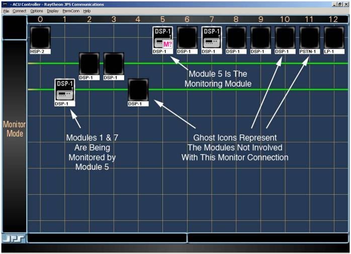
Figure
2‑9 Monitor Mode Setup Screen
In the figure above, the operator has first clicked on the
number 5 in the column heading area (to configure Module #5 as the module that
will monitor other modules), and then on modules 1 and 2 to select them to be
monitored. The modules that are not
involved in the Monitor Connections are all depicted with ghost icons.
Three modules have normal icons:
§
Module 5 is the Monitoring Module.
§
Module 1 is being monitored; it’s part of a current
net.
§
Module 7 is also being monitored; it’s in the “idle
row”, not part of any current net.
Click any ghost icon to add that module to the group of
modules being monitored; the ghost icon will change to the normal icon. When the selection of modules is complete,
click on the monitoring module one more time to leave the special set up mode.
The question mark in the monitoring module will be replaced by a headset image
over the “M”.
The monitor feature is independent of current system
connections; modules can be set up to be monitored whether or not they are currently
part of a net. If Module 7 in the
figure is later made part of a net, its receive (input) audio will still be
monitored by Module 5. If the net
consisting of Modules 1 & 4 is broken, Module 1 will still be monitored by
Module 5.
While still in the Monitor Mode, a click on a normal module
icon will stop monitoring that particular module, and the icon will verify the
change by returning to the ghost version.
If the right mouse button is currently configured to disconnect, a right
mouse-button click will also end monitoring.
Monitor Mode is always specific to the module that was
selected by its column heading. While
in Monitor Mode, you can select a different monitoring module by clicking on
the number of another module in the column heading area.
One common use of the Monitor Mode is for the operator of the
ACU Controller to set the ACU so the HSP-2 monitors all modules. The operator, stationed near the ACU, can
then listen to all traffic and be prepared to respond quickly to a changing
situation and any requests from system users.
2.2.4.2
Exiting the Monitor Mode
There are four equivalent ways to exit Monitor Mode:
§
Click the module icon of the monitoring module.
§
Click its column heading.
§
Press your computer keyboard Esc (escape) key.
§
Click in the net area where the word “MONITOR” is
displayed.
Monitor Connections do not interfere with any other type of
connection.
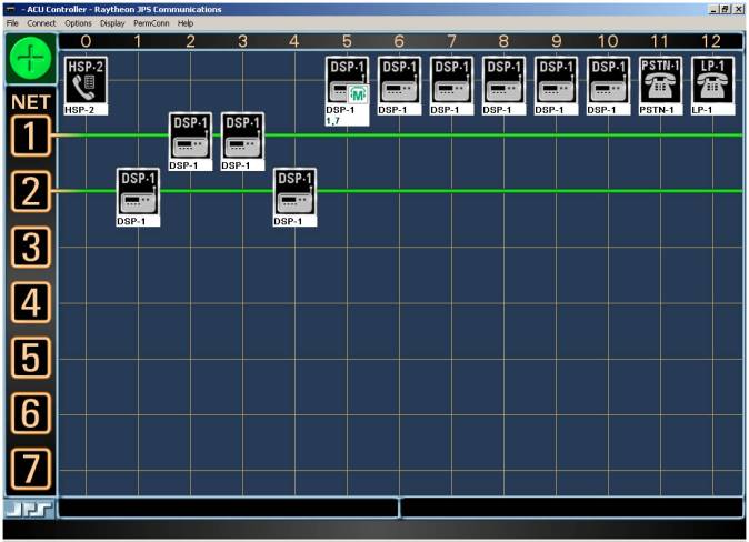
Figure 2‑10 Monitor Indication
Figure 2‑10 shows the standard ACU Controller screen after the
Monitor Setup Mode has been exited.
Note that the icon for Module 5 shows that it is a Monitoring Module and
also lists the numbers of the modules being monitored.
Permanent Connections provide extra security to a net. An extra step must be made by the Controller
operator to break a net that has been turned into a Permanent Connection. A further level of security can be gained by
making the creation and removal of Permanent Connections a password protected
feature. (See Section 4). When a
module is a Permanent Connection, a special small icon is displayed on top of
the module icon, and it cannot be disconnected from any current net by the
normal right-click method. See the figure below.
Note: The Permanent Connection status given to a
net applies only to the ACU Controller that sets that status on the net. For example, it does not prevent a user from
removing himself from the net via DTMF, nor does it prevent changes to the net
by a second Controller if the ACU is being controlled over Ethernet. DTMF control can be disabled on a
module-by-module basis. See the ACU
manual for details.
To form a Permanent Connection, pull down the “PermConn” menu
and select a net number. All modules in the net not in Priority Connections
will then be assigned Permanent Connection status. A net must already be formed before it can be made a Permanent
Connection.
To remove the Permanent Connection status from any net,
simply repeat the procedure. Selecting
the net number from the “PermConn” menu acts as a toggle, first adding, then
removing, the Permanent Connection status from the selected net.
Permanent Connections can only be applied to normal nets;
Priority Connections cannot be protected in this way. If a net is assigned Permanent Connection status while one of its
members is in a Priority Connection, only those modules not in the Priority
Connection will receive the PC icon and status.

Figure 2‑11 Permanent Connection Icon
The ACU can be interconnected via Ethernet (LAN, WAN,
Internet, Wireless LAN etc.) to another ACU, or to a radio or any other
four-wire device. If two ACUs each have
Ethernet connectivity to a network, then it’s possible to cross connect any module
in one ACU to any module in the other ACU, allowing interoperability throughout
any area within reach of the network.
This Ethernet connectivity is established by wiring a DSP-1
module to a JPS NXU (Network Extension Unit) channel. An NXU channel connects any 4-wire device to an Ethernet interface. Consult the equipment manual or the JPS
website (www.jps.com) for more information
about NXU devices, such as the NXU-2.
A special module icon is available to clearly indicate any
DSP modules that are connected to the Ethernet via an NXU channel. It’s provided with the other custom icons on
the ACU Controller CD. See Section 3.3
for details regarding custom icons.

Figure 2‑12 NXU
Custom Icon
When the PSTN-1 is connected into a net, the PSTN-1 Dial
dialog box appears, prompting the ACU Controller operator to enter the desired
telephone number.
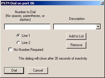
Figure 2‑13 PSTN Dial Dialog Box
To place a call, type the phone number in the “Number To Dial” field,
select Line 1 or Line 2, and click the “Dial” button. Do not include spaces or punctuation in the phone number. A number can be retrieved from the speed
dial database; click on the small button at the end of the “Description” field
to view and select current speed dial entries.
Line 1 and Line 2 refer to which of the two available PSTN-1
ports is to be connected. Only one of
them can be in operation at any time.
See the ACU-1000 or ACU-T manual for details.
After you have typed in a phone number, you can also store it
in the speed dial database for later use.
Type in the “Description” field the associated description you want
saved with the number and click the Add To List button. If you do not supply a description, the
phone number itself will be used as a default description.
To recall a stored phone number, select a description from
the list. The phone number associated
with the description will appear in the “Number To Dial” field.
You can also remove a number from the list by selecting its
description, then clicking the “Remove” button.
Phone numbers are stored in the preferences file (see Section
6.4).
When the PSTN-1 is used with a four-wire circuit, there is no
number to dial, and usually no need to terminate the net when the connected
phone hangs up (goes “On Hook”).
Therefore, 4W PSTN connections operate more like other system
connections; the net stays in place until the ACU Controller operator removes
the PSTN from the net.
The following assumes the PSTN-1 module being connected is
set to 4W rather than 2W. See Figure 3‑2.
To create a 4W connection, click on the PSTN-1 icon and
another icon or net number. The PSTN
Dial dialog box will appear. Click on
cancel and the dialog box will disappear, and the PSTN net will be formed. If the PSTN-1 is set to 2W and the “Cancel”
button pressed, the entire operation is canceled.
If it is desired the 4W connection remain in effect until
broken by the ACU Controller operator, the inactivity timer for the PSTN-1
module should be set to zero (off).
Otherwise the connection will be broken if no activity is detected from
either party for the set timer duration (see Figure
3‑2).
Some two-wire leased lines and “ringdown” lines do not
require you to dial a phone number. To
accommodate these lines, select the “No Number Required” option from the PSTN
Dial Dialog Box. It may be advisable to turn off the PSTN inactivity timer (set
it to zero via the settings screen) if you want the connection to remain in
effect until intentionally broken.
Otherwise, the system will break the connection if no activity is
detected for the set period.
When the ACU Controller is booted up, it queries the
associated ACU regarding its present module settings as well as the states of
any module-to-module connections. The
ACU Controller then configures itself to match. The operator has the option of resetting the system to the
configuration that existed when the ACU Controller was shut down by requesting
“Restore
Last Config” from the File pulldown menu (see Section 1.6). If the ACU
is not turned on, or the RS-232 cable not yet connected, the message area in
the lower right corner of the screen instructs the user to verify the
communications path to the ACU.
The ACU Controller is often installed in a laptop computer
and used to control an ACU-1000 housed in a transportable case. It is possible the power to the ACU-1000
will be inadvertently lost. When the
ACU-1000 power is restored, it is reset with no module-to module
interconnections. Because the laptop
can run on the laptop’s batteries, it continues to function throughout the
power failure. Instead of reconfiguring
to the ACU-1000 reset state, the ACU Controller instead re-establishes the
pre-power cycle interconnections. The
only exception is any PSTN-1 connections in existence when the ACU-1000 or
ACU-T power was cut cannot be restored.
If the ACU power is maintained while the power to the
computer housing the ACU Controller is cycled (or the program is turned off and
back on), the ACU retains its connections, and the ACU Controller configures
itself to match. However, some special
connection features such as Vertical, Priority, or Permanent Connections are
controlled entirely by the ACU Controller, so they will not show up on the
screen after the program configures itself to match the current state of the
ACU. If any of these features are being
used, select the “Restore Last Config” option from the File pulldown menu (see
Section 1.6). The screen
will be updated to reflect what was current when the ACU Controller was shut
down.
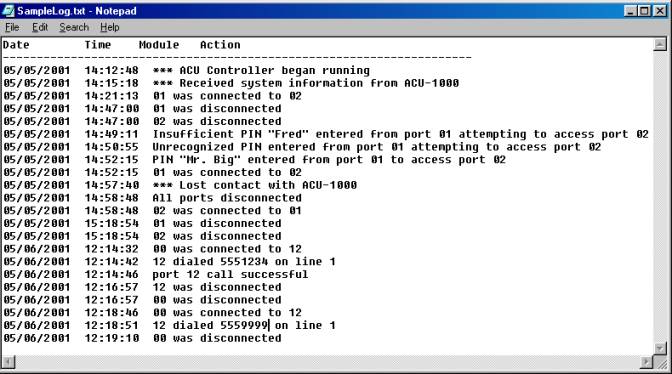
Figure 2‑14 Sample Log File
This is a sample log made by a test system in the JPS Systems
Engineering lab. In this test system,
there are DSP-1 modules installed at extensions 01 & 02, and a PSTN-1
module at extension 12. The log entries
begin when the ACU Controller is launched (this log is for an ACU-1000; a
similar log for an ACU-T would not include any extensions higher than “05”):
·
At 2:12 PM, the ACU Controller begins operation.
·
A few minutes later, the ACU Controller has
automatically queried the ACU regarding its current status, and the ACU has
uploaded its current configuration to the ACU.
·
At 2:21, the ACU Controller Operator connects module #1
to module #2. Normally, there is no way
to differentiate between an ACU Controller operator-commanded connection and
one that was initiated externally by a system user via DTMF commands. However, in this case, module #2 has a
security level greater than 0, so any externally initiated connections would
require the entry of a valid PIN number; see subsequent connections examples.
·
At 2:47, the connection between modules #1 & #2 is
dissolved.
·
At 2:49, a radio user on the frequency of the radio
associated with DSP-1 module #1 attempts to make a connection to module
#2. When this user is asked to enter
his pin number, he entered the PIN number associated with the USER ID “Fred” on
the PIN number database. Unfortunately
for Fred, his PIN number does not have a security level high enough to connect to module #2, so
access is denied. Note that the USER ID
is listed in the log, rather than the associated PIN number. This prevents operator access to the PIN
numbers, which may be password protected.
See Section 4 for more information about PIN security.
·
At 2:50, a radio user on the frequency of the radio
associated with DSP-1 module #1 attempts to make a connection to module
#2. When this user is asked to enter
his pin number, he entered a number that’s not on the PIN database. Again access is denied.
·
At 2:52, another attempt is made to connect to module
#2 via module #1. This time, the PIN number
entered is associated with the USER ID “Mr. Big” from the database. Mr. Big’s PIN number has a high enough
security rating, so this time access is granted.
·
At 2:57, the ACU power is turned off and back on,
simulating a momentary power glitch.
The ACU Controller is installed in a battery backed-up laptop computer,
so its power is not affected.
·
At 2:58, the ACU reports that all of its modules are
disconnected (which always occurs after a power outage).
·
Again at 2:58, the ACU Controller automatically commands
the ACU to re-assume the configuration that was in effect when it lost power:
modules #1 & #2 connected together.
·
At 3:18, the current connection is broken, either by
the ACU Controller operator, or by “Mr. Big” at module #1 or the other user at
module #2. Either of them could enter
the DTMF characters “* #” to break the connection.
·
The next day, the ACU operator uses the HSP-2 module to
initiate a call to the phone number 555-1234 via line 1 of the PSTN module
installed at extension 12. A few seconds
later, the system indicates that the call went through as desired.
·
The call is terminated at 12:16, either by the operator
of the ACU Controller, or by a “* #” entered by either party of the call.
·
At 12 18, another call is initiated via the HSP-2. This call is not successful and the HSP-2 to
PSTN-1 connection is automatically dissolved at 12:19 by the ACU Controller.
An ACU that is connected to a Network via the ETS-1 can be under
the simultaneous control of a number of operators, each running an ACU
Controller program on a computer connected to that same network. Each operator will be able to view the
current ACU connections on his screen, and will see the changes made by the
other operators.
If two operators attempt to make changes at the same time,
only the command received first by the ACU/ETS-1 will be honored. If an operator sends a command while the
ACU/ETS-1 is busy with commands from a second operator, the first operator’s
changes are not made and he receives this message on his lower-right message
screen: “ETS-1 was busy, please try again”.
This signals the operator that other changes were being made and that he
should check to see what those changes are, and if the command that the
operator had sent is still appropriate, it should be resubmitted. Note that a requested change will not affect
what appears on the screen if the request is denied.
There are a number of features that function differently when
a single ACU is under the control of multiple ACU Controller programs. These differences are all based on the fact
that some aspects of these features reside in the ACU Controller and not in the
ACU; therefore this information can not always be shared with the other ACU
Controllers. Included in this
information are speed dial databases, passwords, special module icons or names,
as well as some connection information as explained below.
2.6.2.1
Permanent Connections with Multiple ACU Controllers
When any net is given Permanent Connection status by the ACU
Controller, extra steps (which may include the entry of the correct password)
must be taken to break the connection at that ACU Controller. This Permanent Connection status has no
effect on other ACU Controllers that are in command of the same ACU. The screens of these other ACU Controllers
do not even reflect the Permanent Connection status.
2.6.2.2
Priority Connections with Multiple ACU Controllers
When multiple ACU Controllers are connected to a single ACU,
and an existing net is converted by one of the ACU Controllers into a Priority
Connection, this will be shown on all of the screens.
However, if an additional ACU Controller subsequently
connects to the ACU, its screen will not reflect the Priority Connection
condition. Instead, it will reflect the
actual current connection status; it will show the two priority connection
modules connected in their own net, and not connected to any other
modules. When the priority connection
is then broken, this late-connecting ACU Controller will then show the same
connections as the other ACU Controllers.
2.6.2.3
Vertical Connections with Multiple ACU Controllers
When multiple ACU Controllers are connected to a single ACU, and
two existing nets are connected together into a Vertical Net by one of the ACU
Controllers, this will be shown on all of the screens.
However, if an additional ACU Controller subsequently
connects to the ACU, its screen will not reflect the Vertical Connection
condition. Instead, it will reflect the
actual current connection status as a single net containing all of the modules
that comprise the Vertical Net. If the
Vertical Net is broken, all ACU Controllers will then show the individual nets.
The ACU Controller allows you to change the settings of any
HSP, DSP, RDI, PSTN, or LP module installed in your ACU.
Each of the modules has a settings screen (see Figure 3‑1 for the DSP Module version). To access the settings screen for any
module, click twice on its module icon.
If the right mouse button is set to access the settings screen (see
Section 1), you may also simply right-click once on a module
icon. For the most part, the settings
options are the same as those that are listed in the ACU-1000 or ACU-T manual,
though the ACU Controller is able to provide a few additional options.
Each module setting can be individually controlled via the
settings screen; changes will not take effect until either the Apply button or
the OK button is clicked. “Apply”
changes the setting but retains the setting screen; “OK” must still be clicked
to make the change permanent. When OK
is clicked, the settings in the ACU change and the new settings are stored in
the ACU. If the ACU is then turned off,
it will revert to these new settings when power is re-applied. If you click the Cancel button, any changes
entered will be aborted.
The description and
color settings are not settings that are
stored in the ACU; they are only included to help identify module icons on the
ACU Controller screen. The same is true
for custom icons; they are stored only in configuration files of the ACU
Controller software.
All of the available values for each settings option are
available as pull-down menus. The
factory default settings are noted, and any setting that is not currently
available is grayed out (such as COR Sampling Width when the COR Sampling
feature is disabled).

Figure
3‑1 DSP-1 Module Settings Screen
The “DSP Help” button brings up a PDF file to guide an
installer through a basic radio interface setup. The “Open App Notes” button allows the user to select any of the
available Applications Notes for review or printing. Both functions use PDF files.
The settings screen functions are explained in detail in the
following paragraphs.
There are seven color choices for each icon: gray, red,
orange, yellow, green, cyan, blue, and magenta. Change an icon’s color by clicking on the color button at the top
right of any settings screen. As you
click, the colors will cycle. The
default color for all module icons is gray, so the color button will initially
read “Gray.”
The description field is used to change the text description
of any module icon. The default
description is the module type; in Figure
3‑1, it is “DSP-1”.
At the bottom of each module icon is a label displaying the
description. Most of the time, only as
much text as will fit in the label will be displayed. The full description typed into this field will be displayed in
message area 1 whenever the cursor passes over the icon. If the “Hover Icon Description” feature is
enabled, the full description will also be displayed beneath the icon whenever
the cursor hovers over the icon.
Use the “Custom” field at the top of the settings screen,
along with the accompanying buttons, to change a module icon to a custom
version. You will be prompted to
specify the directory where the icon image files are stored. The program will lead you to the “Icons”
subdirectory, where the standard icons and a variety of other icons are stored.
You can apply the same custom icon to any number of modules.
3.3.3.1
Custom Icons
The button at the right of the Custom Icon field can be used
to browse all available icons. Any user-made
icons can be stored in the same file for retrieval and use. The program will automatically stretch or
compress custom icons to fit the required shape factor. The files themselves
should be Windows or OS/2 compatible bitmap files, with a .bmp extension. They
are not restricted to a certain color depth or resolution.
The bitmap files will be stretched or compressed to fit the
following sizes (in pixels):
§
800 x 600 mode: 48
x 53
§
1024 x 768 mode: 61
x 68
§
1280 x 1024 mode: 76
x 90
In 26-module mode (dual-chassis, Master/Expansion mode), the
widths will be 24, 31, and 39 respectively. The heights remain as listed above.
Icon bitmap files made at the proper form factor will produce
the best results as both stretching and compression of images to a different
form factor can affect clarity. If it
is possible that the same custom icons will be used with more than one screen
size, make the icons appropriate for the largest of the sizes to be used. It’s preferable to compress them to yield
smaller sizes rather than stretch them to create the larger sizes.
All settings for all modules will be saved in a stored configuration (see Section 1) and will be restored when that configuration is
loaded.
An ACU-1000 or ACU-T module can be quickly configured using
pre-stored template files. A number of
DSP Module templates are supplied by JPS covering a variety of frequently-used
radios. Alternatively, the user may
create and store templates.
Included with the ACU Controller CD are DSP Module templates
that contain optimum radio setup values as determined by the JPS Systems
Engineering Department. These settings
are optimized when the specified radio is used with the conjunction with the
radio configuration parameters and interface cable schematic as defined by the
Applications Notes associated with the radio.
With templates, you
can save and restore all settings for an individual module. Once a template is saved, you can recall
those settings at any time and apply them to any module of the same type. One
example for the use of templates is to store optimal DSP-1 settings for various
types of radios. Whenever one of these
radios is installed in the system, the appropriate template can be quickly
loaded to set up the associated DSP-1 module.
Note: Templates do not affect Module Security Levels.
To save a template, click the “Save” button in the settings
screen. When prompted, type in a short
name for the template, which could include the module type and some other brief
description, perhaps the name of the type of radio it represents.
Changes made in the settings screen before clicking “OK” or
“Apply” will be saved in the template, but the module’s actual setting will not
change unless and until either the “OK” button or “Apply” button is clicked.
The description and color settings are not saved in templates
and must be set separately for each individual module.
To load a template, click the “Load” button in the settings
screen. When prompted, select the
template name. You can only load a template
of the appropriate module type. Be sure
that you want to load the template before selecting it, because as soon as you
do, the templates settings will replace the current module settings. If you may want to revert to the
pre-existing settings, use the “Save” button to store the current settings
before selecting a new template to load.
The JPS-supplied DSP Module templates have the same name as
the radio model they apply to, and all have Application Notes. You should view the Application Notes for the
radio model before loading its template.
To browse the notes, click on “Open App Notes”.
Note: Any other changes you have made before
loading a template will be aborted.
Only the settings in the template will be installed.
The only exception is the
Module’s Security Level setting.
Security Levels are not stored in Templates.
A Module’s Security Level is not changed when a Template is
loaded.
This button brings up basic instructions for interfacing a radio
to the DSP Module. The instructions
include flow charts that guide a basic interfacing procedure both when the
JPS-supplied radio templates and Application Notes are available and when they
are not. The DSP Help document is
provided in PDF format.
The “Open App Note” button allows the user to browse to
Application Notes that are currently stored with the ACU Controller. The files are named for the associated radio
model. Open any file to view in PDF
format.
The buttons “Hang Up” and “Dial” reside in the lower left
corner of the PSTN-1 settings screen (below).
These buttons may be used to change telephone connections without
breaking an existing cross-connection between a PSTN-1 and another ACU system
interface module. For example, the
operator may create a PSTN-1 to DSP-1 net.
The operator is monitoring the DSP-1 and when requested, terminates the
current call using the “Hang-up” button.
The operator can then create a new telephone link using the “Dial”
button. During this process, it’s not
necessary to remove the PSTN-1 from the current net.
In the PSTN settings screen shown, these two pushbutton
controls are “grayed-out”, indicating they are currently unusable. They are functional only if there is the
PSTN-1 is currently part of a net.

Figure
3‑2 PSTN-1 Settings Screen
.
The ACU Controller has a special dialog box (see Figure 4‑1) that allows you to change the security level of any
module, add, remove, or change PIN numbers (and associated User IDs), and
change the security mode of the ACU. To
access the Security Settings dialog, select Pin Settings from the Options menu.
Consult the ACU manual for information on how the security
system works and an explanation of the Exclusive and Priority modes.
As with the module
settings screen, changes will not take effect until the OK button is clicked,
and the Cancel button will discard any changes. The security information is saved, along with the module settings
and current connections, in configuration files (see Section 1.6). This means
that each time the ACU Controller is launched, the desired configuration must
be loaded in order to retrieve the PIN security database.
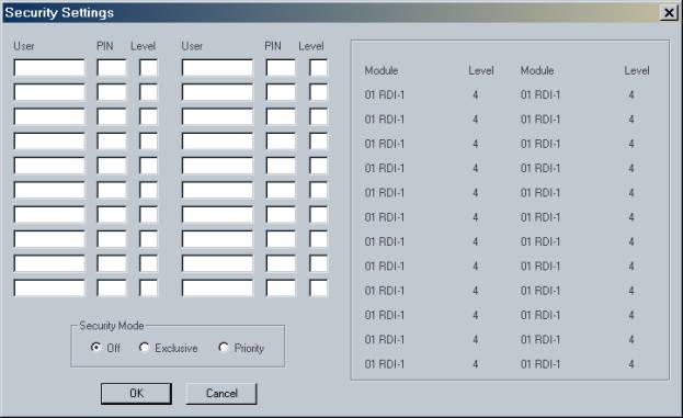
Figure 4‑1 Security Settings Screen
When a connection is attempted via DTMF with any module
having a security level higher than zero, a PIN number is requested by the
system. The log file (see Section 1.8.3) records when this happens. To maintain the security of the passwords, the associated User
ID, rather than the password, is listed in the log.
The Security Settings Dialog Box can itself be password
protected (see Section 4.2). When
protected, the operator will be prompted for a password before the screen can
be viewed or any changes made.
Access the password dialog box (shown below) by selecting Password
Protection from the Options menu.
This allows you to apply password protection to:
§
Security Settings
§
Permanent Connections
§
The Module Setup Screens
All are protected by the same password, and once any one of
these Password Protection options have been enabled, the password will be required
to enter the Password Protection screen in order to change these settings or
the password itself.
To add or change the password, it must be typed twice and
then the Apply button must be selected.
The password protection information is encrypted and stored in the
preferences file (see Section 6.4) and is loaded each time the ACU Controller is
launched.
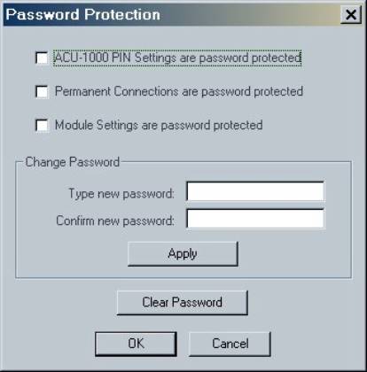
Figure 4‑2 Password
Protection Dialog Box
All commands in the ACU Controller can be accessed with the
keyboard. It can be used in place of,
or in conjunction with, the mouse or touch screen.
Making and breaking connections with the keyboard consists of
the same operations that would be used with the mouse, except each mouse click
has a corresponding keystroke series: The “##”
symbol represents a two-digit module or net number in each command.
§
Click on module icon (left-click): c##
§
Right-click on module icon: d##
§
Click on net number icon: n##
§
Right-click on net number icon: b##
§
Click on column heading (enter/exit Monitor Mode): m##
§
Toggle Connect / Disconnect Mode: t
These commands are
case-sensitive; all must be lower-case.
For example, clicking on one module and then another puts the
two in a net, so to connect module 1 with module 2, type c01c02. To add module 3 to net 1, type c03n01. To disconnect module 4, now type d04. To enter Monitor Mode for module 5, type
m05.
Note: The keyboard input is affected by anything
that would affect mouse input. If the
right mouse button is set to access module settings instead of disconnecting,
the command d01 will go to the settings screen instead of disconnection module
1. (Normally, c01c01, two left clicks
on module 1, would access settings.)
Likewise, if the Connection Indicator is in Disconnect Mode, the command
c01 will disconnect module 1.
The ACU Controller’s pull-down menus can be accessed with the
keyboard in the same way as all other Windows programs. To enter the menu, press Alt, followed by the
key for the underlined letter in the menu you want to access, then the key for
the underlined letter in the desired command.
Some commands require an additional key if another sub-menu is present. For Windows XP, the underlining does
not show up until the Alt key is pressed.
Figure 5‑1 Options Pull-Down Menu
For example, Alt O will select the Options menu. Use the keyboard to select any of the
various commands. Alt F will turn off voice
prompts. Press Alt OF with no delay in
between. As in all Windows programs,
these commands are not case sensitive; you can use either upper or lower case
letters.
The only other keyboard command is Esc (ESCAPE). Pressing Esc will do the following things if
appropriate considering the current state of the program & system:
Ø Deselect
any selected module
Ø Clear
keyboard input
Ø Exit
Monitor Mode
This section discusses information not covered in the
previous sections, including additional options. Understanding this section is not necessary for normal operation
of the ACU Controller.
In order to maintain a consistent and accurate interface, the
ACU Controller cannot act on a command from the user until the ACU has
validated it. It would be dangerous for
the ACU Controller to assume a command will work, indicate that it has to the
operator by performing the operation on the monitor, and then sending the
command to the ACU. Therefore, commands
are always passed to the ACU and a response is then sent back, which sometimes
can be slow, especially if the ACU Control Processor Module is currently
otherwise occupied. The user may have
to wait for periods of several seconds, or perhaps close to a minute,
especially when loading a configuration that has a large number of
modules. The speed of communication is
entirely limited by the ACU itself and not by the computer running the ACU
Controller.
Remember the ACU Controller cannot afford to miss any
information from the ACU. This is why
the serial cable must be plugged in at all times during operation. If the ACU Controller does miss something,
it can become out-of-sync, and you will need to use the Retrieve Current
Configuration command.
The ACU Controller uses a variety of pre-recorded sounds in
the form of .wav files. They are all
located in the “Sounds” directory right off the installation directory. If desired, these sounds can be changed by
renaming the files and adding own new ones, using the original sound file names
them regardless of whether they are the original files or ones the user
supplied.
If you do change the sounds, be extremely careful not to use
.wav files that are too long. Be sure
to test (listen to) the new files with another application; supplying invalid
.wav files may cause the ACU Controller to crash.. The ACU Controller looks for these names and will play
The customizable features of the ACU Controller are all
stored in the preferences file called “ACU_Controller.cfg,” located in the ACU
Controller’s installation directory.
You can delete or rename this file to reset all preferences back to
their defaults; this will also clear the password and clear the stored phone
numbers. (Exit the program before
deleting or renaming this file from outside the program.) At startup, the ACU Controller will
automatically create a new file (with default settings) whenever you delete or
change the old one; you will then be able to change the preferences.
The defaults are:
§
Sound: On
§
Right mouse
button: Disconnects
§
COR Reporting: On
§
PTT Reporting: On
§
Animation speed: Medium
§
COM port: COM1
§
Password
protection: None
§
Hover Messages: On
§
Auto Connect: Off
This section lists all of the various cautionary and
instructional messages that may appear on the Controller screen, along with an
explanation for each.
An attempted connection could not be made; because one or
more of the modules involved has conferencing turned off and already is
connected to a module. This message will only occur in response to a request
from the Controller, not from radios or from the HSP-2.
The user tried to change the password, but the second entry
did not match the first. The password has not been changed.
This message indicates an error with Windows. The Controller
will exit after displaying this message. The user should try again, or
reinstall Windows.
Clicking yes will connect all modules in one net.
Clicking yes will disconnect all modules from their present
net.
The user selected a new COM port, but the new Port did not
work correctly. Possibilities are the
requested port either is already in use by another application or does not
exist.
This message indicates an error with Windows. The Controller
will exit after displaying this message. The user should try again, or
reinstall Windows.
The user tried to Load Configuration, but the Controller is
not aware of the ACU's current configuration or not in contact with the ACU.
The incorrect password was not entered, please re-enter the
password and try again.
The user attempted to load a saved configuration that is not
compatible with the ACU current compliment of plug-in modules. This can also
occur on a Restore Last Configuration command.
A saved configuration cannot be loaded if the modules currently
installed in the ACU are not the same type and location (plug-in slot) as were
installed when the configuration was saved.
The user tried to load a saved configuration that was made
with an incompatible earlier version of the program that used a different configuration
file type.
The user tried to Load Configuration, but the Controller
could not open the file. The file may be in use by another application of the
Controller, or some other error occurred. The user should try again.
The user exited the Select COM Port dialog while no COM port was
open. Just a warning message, which assumes the user wanted to establish a
useable COM port selection.
The user selected a new COM port, and it worked.
The Controller did not detect a preferences file and created
a new one with the default settings.
The user tried to Save Configuration without having any info
from the ACU.
The user tried to view the Log, but the computer has no
default text viewer set. User will have to either associate some application
with .txt files, or explicitly open the log in some text editor.
An attempted connection could not be made, because the ACU is
out of free busses. This message will only occur in response to a request from
the Controller, not from radios or from the HSP-2.
The user tried to create a New Log, but cancelled or did not
supply a name. This will cause logging to stop until a new file is chosen.
The user has successfully changed the password. This is a
confirmation dialog box.
The user has pushed the Clear Password button, and the
password has been cleared. When this happens, the Controller will turn off
password protection altogether.
Ensures the operator really does want to reset the ACU
Controller configuration to the current ACU configuration.
The user tried to Save Configuration, but the Controller
could not create a file. Not enough disk space could be the problem, but this
could also be a Windows error. The user should try again.
The user tried to load or save a template (stored module
settings), but the file could not be opened for the same possible reason listed
above. The user could try again.
The user tried to load a template into a module of the wrong
type. For example, the template was the settings for a DSP module, and the user
tried to load it into an RDI.
The CPM-2 software is too old and does not support some
necessary commands. The Controller will exit after displaying this message.
The user tried to change the password to something too short.
The password has not been changed.
The user tried to add another entry into the phone book, but
it has reached its capacity.
The user tried to view the Log, but some sort of file error
occurred. As with Load Configuration, the possible explanations are: the file
is in use or Windows error occurred. The user should try again.
This section lists changes in the ACU Controller software and
the revision number when they were added.
The history documents only general releases of the software, not
revision numbers related to internal company use.
·
Added many more Radio Template & Application Notes
files
·
Minor bug fixes
7.1.2 Revision 4.0
(recalled)
·
Improved setting screens with pull-down menus
·
DSP module settings screen now supports:
o
Pre-stored radio templates from JPS
o
Pre-stored Applications Notes
o
“DSP Help” button to guide radio interface &
configuration
·
Connect menu now includes “Recently Connected” list for
quick reconnection
·
Variable BAUD Rate
·
Improved Graphical Design
·
Screen size automatically maximized at installation
·
“Hover Icon Description” feature added to Display Menu
·
Support added for HSP-2 and HSP-4 adjustments
·
Reorganization of menus, including addition of new
“Connect” menu.
·
CPU usage greatly reduced to allow increased
multitasking of host computer.
·
Minor Bug fixes.
The main changes to this
version were Win 2000 compatibility and the addition of features related to
Ethernet connectivity.
·
Windows 2000 compatibility added.
·
New Options Menu and Dialog Boxes allow entry of the IP
addresses associated with all ACU-1000s to be controlled via Ethernet.
·
Added NXU custom icon to help identify DSP modules that
are dedicated to cross-connections via Ethernet.
This was the initial
release of the ACU Controller. It
replaced the “ACU Console Software”